Pagine

Post più popolari

30 Nov 2012


 Self Bias


FET-Self Bias circuit


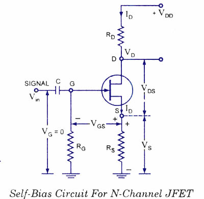
This is the most common method for biasing a JFET. Self-bias circuit for N-channel JFET is shown in figure.


Since no gate current flows through the reverse-biased gate-source, the gate current IG = 0 and, therefore,vG= iG RG = 0


With a drain current ID the voltage at the S is
Vs= ID Rs


The gate-source voltage is then


VGs = VG - Vs = 0 – ID Rs = – ID Rs


So voltage drop across resistance Rs provides the biasing voltage VGg and no external source is required for biasing and this is the reason that it is called self-biasing.


The operating point (that is zero signal ID and VDS) can easily be determined from equation and equation given below :


VDS = VDD – ID (RD + RS)


Thus dc conditions of JFET amplifier are fully specified. Self biasing of a JFET stabilizes its quiescent operating point against any change in its parameters like transconductance. Let the given JFET be replaced by another JFET having the double conductance then drain current will also try to be double but since any increase in voltage drop across Rs, therefore, gate-source voltage, VGS becomes more negative and thus increase in drain current is reduced.

21 Nov 2012

...some technical notes about balanced DACs


Balanced-Ouput DACs and Tubes


Back to DACs. Last time we looked at this topic, we saw tube circuits picking up their input signal from DACs with a single output, which was either a voltage or a current output. So far, everything has been fairly straightforward; however, when we come to DACs with balanced outputs, we face a few twists. For example, most CD players and stand-alone DAC units that sport balanced-output DACs are not balanced themselves at their outputs, with a single RCA jack per channel as an output. Here is another oddity: the output of a non-balanced DAC is usually referenced to ground, with an output that expects to see 0V. On the other hand, balanced outputs are usually referenced to some positive voltage, say 2.5V.


So, the first question is: Why use balanced-output DACs when the final output is unbalanced? The answer is that we can get better performance at less cost. When the DAC's two phases of output signal are summed together, the summing circuit’s intrinsic common-mode rejection ration (CMRR) will ignore the noise that is common to each balance output, amplifying only what is not common in its single-ended output, which affords an improved signal-to-noise ratio. In other words, the power-supply noise falls out of the mix, so a simpler and cheaper DAC power supply is allowable.


CMRR and differential amplifiers are seldom mentioned in tube circles. The following illustrations expose a differential amplifier’s functioning.


Now, we can see how the differential amplifier, by ignoring what is common and amplifying what is different between balanced inputs, can produce a clean output waveform from two dirty signals. (Note that when both inputs see the same voltage, the output falls to zero.)


The next question is: Why do so many new DACs have outputs that are not at the ground potential? Historically, the trajectory that DACs have been on started with many pins and many support devices and many supply voltages to the desired end of only a few pins and only one power supply voltage. The reasoning is easy to decipher—it’s both easier and cheaper that way.


The makers of digital-audio gear complained of the cost of all the required prop-up components, such as decoupling capacitors and trimming potentiometers, and excessive complexity (they had been spoiled by OpAmps, which are cheap and easy to use); and the makers of DACs wearied of the many user-support headaches, as their DACs failed to deliver the advertised performance due to their customers' lack of understanding and sloppy construction practices. In other words, no one was happy. Thus, we are getting DACs that are simpler, cheaper, and easier to implement.


Old New


In the above DAC footprints, we can see the move to smaller and simpler. (Each of the pins labeled "DECOU" and pins 16 and 17 require shunting capacitors; and the DAC requires three power supply voltages, +5V, -5V, and +15V.) However, a single power supply voltage of 5V cannot accommodate a ground-voltage-referenced output, as there is no negative-power-supply voltage to support a current source to pull the output down to ground level. (If the output were inductively loaded, however, such a DAC would become possible; but who— other than an audiophile —wants an expensive, heavy, hum-attracting choke in his or her iPod or portable CD player?) Thus, many of the new, streamlined DACs have an output referenced, not to ground, but instead at B+ voltage divided by two (or some value close to two). For example, if the DAC’s power supply voltage is 5V, then its signal outputs will be at +2.5V. So is a coupling capacitor needed to block this large DC offset? No, because the balance-to-unbalanced circuit will drop out the 2.5V DC offset along with the noise, as the shared DC offset voltage is effectively a common mode signal.


So where the old DACs were complex, requiring many clean power-supply voltages and many bypassing capacitors, the new breed of easy-to-use DACs requires only one power supply voltage, and it need not be perfectly clean for a fairly decent PSRR.


Tubes to the rescue

So how do we use the balanced-output DAC with a vacuum tube output stage? Let's pull back and review. The balanced-output DACs, with internal I-to-V converters and voltage outputs, put out a good amount of signal swing, easily enough to drive the average power amplifier directly. If you need more gain, however, the design of the the tube circuit will have to be fairly complex, as it will have to comprise gain and buffering stages. But if the tube stage does not have to drive a low-impedance load, the following simple circuits will work quite well, converting balaced input into an unbalanced output, while providing a CMRR roughly equal to 1/mu.


In both circuits, the addition of resistor R in the cathode circuit, allows the tube circuit to have its effective reference voltage upped to 2.5V.


In other words, without the DAC, the tube circuit would bias up to where the connection between RK and R would naturally sit at 2.5V at idle. Of course, we are not limited to the two above tube circuits. For example, the Aikido amplifier can be used just as easily:


The input stage of the Aikido is effectively lifted 2.5V off ground by the addition of the extra resistor. By switching to the Aikido we gain all the benefits that the Aikido offers, such as low output impedance, low distortion, and a great PSRR. The only obvious problem is that of too much gain (the previous two circuits also suffer from this), as the balanced signal from the DAC will result in twice the gain we would have gotten from a comparable unbalanced signal source. In the case of the Aikido, the calculation is an easy one: gain roughly equals amplification factor of the input tube, for example, 20 for the 6SN7 and 33 for the 6922.


Another less obvious problem that we might encounter with all these circuits is that the wimpy internal OpAmps in the DAC might not be able to drive such a low-impedance load. Which low-impedance load? The non-inverting outputs (in these schematics at least) have the low-valued resistor that bridges the cathode resistor to ground. This resistor is also in parallel with the low output impedance presented by the bottom triode's cathode in series with the cathode resistor. What can be done? The following circuit unloads the internal OpAmps by the current gain of the transistors used (typically, well over 100).


Oh my, how amazingly creepy: two transistors! Try as I may, I keep forgetting that if a nervous audiophile cannot see a transistor, such as the several hundred in the DAC, the transistors do not exist. Okay now, is there a circuit that isn't so creepy and doesn't have excessive voltage gain and doesn't burden the internal OpAmps within the DACs? (This would be much more dramatic with a beautiful, scantly-clad, showgirl assistance and a shower of sparks...)


What we are doing here is throwing away much of the DAC's output signal, while providing a higher-impedance load to the DAC, and while retaining the high CMRR. Extra touches can take the form of high-frequency-shunting capacitors added to filter away some of the high-frequency noise from the DAC.


(The same buffer/attenuator circuit can be used with the first two circuits shown, the grounded-cathode and SRPP amplifiers.)


On the other hand, if no gain is required, then a much simpler circuit can be used. (Remember, no gain, no pain.)


The Broskie cathode follower has been covered here before, so only a quick recap will be given. This circuit accepts a balanced input, which it converts to an unbalanced, single-ended output (the circuit itself is push-pull in functioning). It offers low distortion and low output impedance and, most importantly in this discussion, a good CMRR figure.


The Broskie CF can accommodate a low-pass filter by adding two capacitors, C1 and C2. These capacitors limit the high-frequency bandwidth, which will help filter away high-frequency DAC generated noise. (I would place the transition frequency at 30kHz with 500pF capacitors.)


Next time

Expect more balanced-output DAC circuits, but with differential amplifiers at their core. (I figure this blog entry is the most that anyone reasonably can digest before rushing off to work or school. I keep striving for "bite sized," but big lunches usually seem to win out. Today I hope I have managed to keep it digestible.)

20 Nov 2012

Design Guidelines for JFET Audio Preamplifier Circuits


Design Guidelines for JFET Audio Preamplifier Circuits
By Mike Martell
N1HFX

The Junction Field Effect Transistor (JFET) offers very high input impedance along with very low noise figures. It is very suitable for extremely low level audio applications as in audio preamplifiers. The JFET is more expensive than conventional bipolar transistors but offers superior overall performance. Unlike bipolar transistors, current can flow through the drain and source in any direction equally. Often the drain and source can be reversed in a circuit with almost no effect on circuit operation.

Transconductance

The ability of a JFET to amplify is described as trans-conductance and is merely the change in drain current divided by the change in gate voltage. It is indicated as Mhos or Siemens and is typically 2.5mmhos to 7.5mmhos for the MPF102 transistor. Because of the high input impedance, the gate is considered an open circuit and draws no power from the source. Although voltage gain appears low in a JFET, power gain is almost infinite.

Drain Characteristics

Even though no voltage appears at the gate, a substantial amount of current will flow from the drain to the source. In fact, the JFET does not actually turn off until the gate goes several volts negative. This zero gate voltage current through the drain to the source is how the bias is set in the JFET. Resistor R3, which is listed in the above diagram, merely sets the input impedance and insures zero volts appears across the gate with no signal. Resistor R3 does almost nothing for the actual biasing voltages of the circuit. When the gate voltage goes positive, drain current will increase until the minimum drain to source resistance is obtained and is indicated below:
Minimum Rds(on) or On State Resistance

The above value can be determined by reading specification sheets for the selected transistor. In cases where it is not known, it is safe to assume it is zero. The other important characteristic is the absolute maximum drain current. Listed below are absolute maximum drain currents for some common N-channel transistors:
  • MPF102 - 20ma
  • 2N3819 - 22ma
  • 2N4416 - 15ma
When designing a JFET circuit, it is highly recommended to prevent the absolute maximum current from being exceeded under any conditions. In design calculations. never use more than 75% of the maximum drain current as specified by the manufacturer.

JFET Design Example 1

For the first design example, we will use an MPF102 transistor with a Vcc of 12 volts. We will allow no more than 5 ma of drain current under any circumstances. For resistor R3, the gate resistor, we will use 1 Meg for a very high impedance across the gate. The gate resistor is normally anywhere from 1 Meg to 100K. The higher values allow the JFET to amplify very weak signals but require measures to prevent oscillations. The lower values enhance stability but tend to decrease gain. Sometimes the value of this resistor needs to be adjusted for impedance matching depending on the type of signal source involved. Because we will only allow 5 ma of current through the drain to source, we will calculate the total resistance for resistors R1 and R2. We will assume the Minimum R
ds(on) to be zero.

V
cc = 12
Minimum R
ds(on) = 0
I
ds = 5 ma

(V
cc - (Minimum Rds(on) * Ids)) / Ids = Total Resistance of R1 and R2
(12 - (0 * .005) ) / .005 = 2400 ohms

To calculate R2, we must select the desired voltage drop across this resistor. it is normally set between 20 to 30% of Vcc. For this example we will set R2 to 25% of the supply voltage (minus any voltage dropped across the drain and source) as follows:

R2 = .25 * Total Resistance of R1 and R2
R2 = .25 * 2400 = 600 ohms (nearest standard value is 560 ohms)
R2 = 560 ohms

R1 can now be easily calculated by subtracting R2 from the total resistance as follows:
R1 = Total Resistance - R2
R1 = 2400 - 600 = 1800 ohms
To prevent oscillations a 10 ohm resistor and a 100uf capacitor were added to isolate the circuit from the power supply. A .1uf capacitor was used for input coupling and a 4.7uf capacitor was used for output coupling. Slightly larger or smaller capacitor values will also give acceptable results. The optional 4.7uf capacitor which bypasses R2 is used to obtain the maximum amount of gain the transistor will deliver. The addition of this capacitor may introduce a small amount of unwanted white noise and should only be used when an absolutely quiet preamplifier is not required.
JFET Design Example 2

In the second design example, we will use an MPF102 transistor to add an additional stage of amplification to our circuit. We will make the following assumptions:

R3 = 1Meg
V
cc = 12
Minimum R
ds(on) = 0
I
ds = 7ma

(V
cc - (Minimum Rds(on) * Ids)) / Ids = Total resistance of R1 and R2
(12 - (0 * .007)) / .007 = 1714 ohms

We will assume R2 to have 25% of the supply voltage.
R2 = .25 * Total of R1 and R2
R2 = .25 * 1714 = 429 ohms (use 470)
R2 = 470

R1 = Total Resistance - R2
R1 = 1714 - 429 = 1285 ohms (use 1200)
R1 = 1200 ohms

A 4.7uf capacitor was used for input coupling and a 10uf capacitor was used for output coupling. Slightly larger or smaller capacitor values will also give acceptable results. The optional 10uf capacitor which bypasses R2 is used to obtain the maximum amount of gain the transistor will deliver. 

By putting our two circuits together we now have a two transistor JFET audio preamplifier with excellent gain and very low distortion. A 10K level control was added to complete the preamplifier circuit. If you decide to use a 2N3819 be aware that the pin-out is different than other JFET transistors

4 Nov 2012

Philips DVD Micro Theater MCD908


.......

More details trickle in. The tube type used is the 12AX7. The MCD908 does in fact hold the very-listenable TDA8920 stereo class-D amplifier module from NXP, not Philips, as I had mistakenly mentioned before (NXP was founded by Philips). The power amplifier derives its power from a fairly large toroid transformer. In addition, the MCD908 will play just about anything that you throw at it:


Playable Discs
Your DVD Player will play:
– Digital Video Discs (DVDs)
– Video CDs (VCDs)
– Super Video CDs (SVCDs)
– Digital Video Discs + Rewritable (DVD+RW)
– Compact Discs (CDs)
– Picture (Kodak, JPEG) files on CDR(W)
– DivX(R) disc on CD-R(W):
– DivX 3.11, 4.x and 5.x
– WMA
– Supported MP3-CD format.
• ISO 9660
• Max. title/album name –12 characters
• Max. title number plus album is 255.
• Max. nested directory is 8 levels.
• The max. album number is 32.
• The max. MP3 track number is 999.
• Supported sampling frequencies for MP3 disc:
32 kHz, 44.1 kHz, 48 kHz.
• Supported Bit-rates of MP3 disc are: 32, 64,
96, 128, 192, 256 (kbps).

Following formats can’t be supported
• The files like *.VMA, *.AAC, *.DLF, *.M3U,*.PLS, *.WAV
• Non-English Album/Title name
• The discs recorded under Joliet format
• MP3 Pro and MP3 with ID3 tag

I actually had the chance to listen to the MCD908 a few days ago. The local Fry's Electronics store sells it, although they apparently didn’t know how to hook it up. So after my friend Glenn and I set things straight, what did I think of the sound? I cannot honestly comment, as all we could listen to was FM radio without an antenna and I could not pick up my favorite radio station. Of course, what interests me most about this little gem is the taking it apart and then modifying it. The tube stage is a somewhat competent, but nonetheless rather silly affair, with the 12AX7 working in a low-gain, high-feedback line stage amplifier.


Before we dig into the actual circuit, let’s look at what brackets the circuit: two fixed voltage dividers. The first comprises the input 47k resistor and the 8.2k grid resistor, which reduces the input signal down to 15% or -16.5dB. The second voltage divider is found at the output and it holds 3.3k and 22k resistors, which reduces the output signal down to 87% or -1.2dB. Why all the attenuation? To do away with the gain from the tube line stage amplifier of course.

The power amplifier does not require a preamp, so the tube circuit’s role isn’t to provide gain, but tube warmth and glow. Why else would you run the 12AX7s so leanly? Why would you drag down the input tube with a 150k load and the output tube with a 25k load other than because you wanted distortion. Yet, the circuit uses a fair amount of feedback.

Well, how do we gracefully back out of the stock circuit? At the very least, I would lose the 12AX7 in a flash and plug a 12AU7 in its place. Then I would change a few parts values, while keeping the existing topology.


The gain is only a bit lower than the 12AX7-based version, but the feedback ratio has dropped hugely, which can only improve the sound. Since the voltage dividers have been scaled back, the power amplifier’s gain would need to be reduced. And because we are running so much more current through the line stage amplifier, the power supply will need some adjusting to achieve the same 200V B+ voltage. Fortunately, the power supply uses a simple RC filter to smooth the B+ voltage.

Ideally, we would lose the stock tube circuit altogether and start fresh. Imagine using an Aikido line amplifier with four tubes glowing through the front window. Or, perhaps, just a single 12B4-based grounded-cathode amplifier per channel, which might just be possible with a good amount of PCB hacking, if there is enough room, as the 12B4 stands 2.375 inches tall in its socket, whereas the 12AX7 stands 1.9375 inches tall. On the other hand, we could fairly easily use a 12AU7 with both its triodes in parallel.


In general, I am fearful of using just two triodes in parallel, as I have always found that I prefer the sound from a single triode. In this case, however, where the original circuit was so off the mark, I am confident that the parallel triode would still be a huge improvement. In fact, I would be willing to test the limits of the high-voltage power supply by using a lot more current and more plate voltage, as shown below.


Much better. Increasing both the plate voltage and the idle current moves the 12AU7 into its more linear region and will allow the line stage amplifier to drive capacitance more readily, not that there are any line outs on the MCD908 (of course, they could be added, with the help of a drill and some skill).

The downside to the heavy current draw is that the power supply will be even more taxed by both the high idle current and the signal-induced current variations, which might subtract from our freshly won sonic gains. An alternative circuit is the constant-current-draw amplifier shown below.


The cathode follower works in an anti-current-phase relationship to the grounded-cathode amplifier, so if the two stages are equally loaded, the net current draw from both stage remains constant. (The key issue is not that the two idle currents match, but that the two signal currents cancel. So the grounded-cathode amplifier should draw more idle current, as the cathode follower will work into both its cathode resistor and the external load impedance.)

The diode, for those new readers, is not part of the circuit during normal use, as it is reverse biased, as the cathode follower’s cathode is more positive than the grounded-cathode amplifier’s plate. But at startup, when the triodes are cold and not conducting, the diode forward biases and conducts, protecting the cathode follower’s triode from cathode stripping. (Do you really want the grid to see +200V and the cathode to see 0V at the same time?) Once the tube begins to heat up, the triodes will conduct and the diode will fall out of the circuit. A 1N4007 will work well in this position.

Now that we have broken free from the dictates of the existing PCB, let’s see what else we could do with two 12AU7s. We do not need much gain, nor apparently do we need an extremely low output impedance. No phase reversal would also be a nice feature for those nervous about such things. (If you think that any recording was made fastidiously preserving the true absolute phase of the performance, well then… Do not get me wrong here. I do believe that phase is quite hearable; I just have no faith in believing that the phase set on the recording will match reality or any other track on the recording.) Well, the above list of desirable attributes screams out for a cathode-coupled amplifier.


True, the above circuit doesn’t use a constant-current source to load the shared cathodes. True, no large negative power supply rail is used to allow for a large-valued cathode resistor. Still, this cathode-coupled amplifier uses a few tricks. First, the input triode’s plate sees the full B+ voltage without any voltage-dropping plate resistor, which would normally unbalance the triodes DC operating points. But in this circuit, the DC balance is restored by presenting the output triode’s grid with a +6V bias voltage. The two-resistor voltage divider also serves to provide a hint of negative feedback, both AC and DC to the output triode.

Now, if you are willing to abide the inclusion/contamination of solid-state devices, then the National Semiconductor LM134/LM234/LM334 3-terminal adjustable current sources are a good choice, as they will source up to 10mA and work with only a few volts across them. Alternately, a FET constant-current source could easily be made up from any FET with an IDSS greater than the desired current draw, as a source resistor will decrease the FET’s conduction to the require value.

I, however, would try the simple cathode resistor first, before I tried to fix that which might not be broken. In fact, I would tackle the cathode-coupled amplifier’s poor PSRR first. In other words, get ready for another Aikido moment.


We lost the negative feedback loop, but we added a feedforward noise-reduction system in its place. In a nutshell, the power-supply noise is injected into the cathode-coupled amplifier’s second input, where it is amplified and phase reversed, so that it cancels at the output triode’s plate.

The output triode still sees the same 6V bias voltage, so the two triodes will still conduct equally. In SPICE simulations, the PSRR improvement was extreme—an over 40dB improvement; expect reality to differ, but with patience and skill, it can be brought in line with the simulation.

The distortion in the SPICE simulation was equally impressive, but then SPICE models are overly optimistic, assuming a perfectly constant amplification factor that does not exist in reality. Nonetheless, I am sure that this circuit would walk all over the original. Well, if that’s true, why don’t I buy an MCD908 and give it a try? Good question. One problem with the MCD908 is that I would not know when to stop. For example, since the line stage amplifier is not really required (the power amplifier easily able to make do without it), why not then use the two tubes for some other purpose, such as a phono stage. See case_riaa_6 for an example.

Imagine what a great little system could be made from such a modification: a turntable and an LCD TV monitor and the MCD908. A perfect bedroom system, perhaps.

Then there is the issue of replacing inferior parts with better parts. And what of the loudspeakers? What sort of crossover do they hold? Before you know it, a lot of time, effort, and money would find itself pouring into the MCD908. Maybe it would be worth it. I would love to find out.


//J
RB


if you're interested in home made tubed DVD Player  see also :

http://maoaudiolab.blogspot.it/2011/10/stunning-tubed-dvd-cd-player-completely.html


you will find a real "giant killer" with this home made device.....

Simple phono 12AX7 tube amp ....and much more....